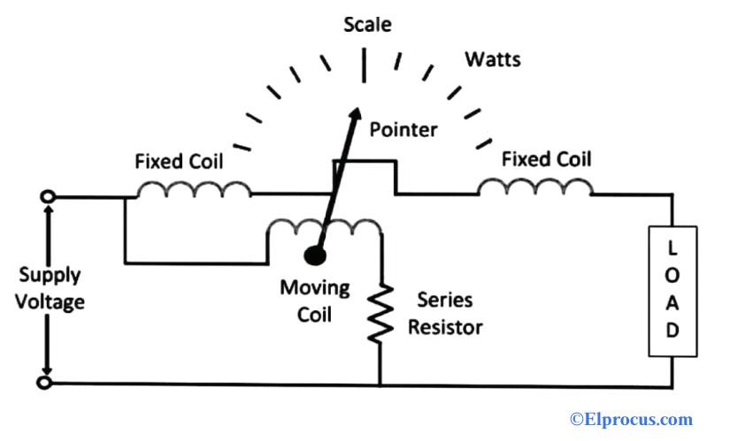
induction type wattmeter diagram
The current in the main winding I M lags behind the supply voltage V almost by the 90-degree angle. The phasor diagram is also shown on the left-hand side of the waveform where current I m lag voltage V m by an angle of π2.

Unit 03 Construction Operation Of Watt Meter Energy Meter
It consists a coil operated contactor C controlled by start and stop push button as shown in the connection diagram below.
. Power in Pure Inductive Circuit. As compared to capacitor voltage type conventional wound type is expensive due to the necessity of the insulations. I 2sc ammeter reading.
At balance Condition Now The other. It supplies the electrical power from generating unit to the distribution unit. Utilities are governed by standard in terms of their system availability and quality of power.
W c Wattmeter reading. Power in RC Series Circuit. In NPN transistor the direction of movement of an electron is from the emitter to collector region due to which the current constitutes in the.
The circuit diagram of the NOR gate flip-flop is shown in the figure below. Thus there exists a time difference between the currents of the two windings. Therefore diode D 2 and D 4 conduct while diodes D 1 and D 3 do not conduct.
The transistor in which one p-type material is placed between two n-type materials is known as NPN transistorThe NPN transistor amplifies the weak signal enter into the base and produces strong amplify signals at the collector end. The following steps are given below to draw the phasor diagram. The primary copper loss is neglected and secondary current losses are zero as.
The schematic representation of a single bit Full Adder is shown below. The phasor diagram for a load of lagging power factor is shown belowLet the receiving end voltage V r be taken as reference phasor and it is represented by OA in the phasor diagram. The V 1 is also obtained by adding the I 1 R 1 r 1 with the voltage drop ωI 1 L 1 in the arm ABThe phasor sum of the E 1 and E 3 or E 2 and E 4 will give the supply voltage.
Therefore the motor operates as the balanced two-phase motor. Diversity factor is defined as the ratio of the sum of the maximum demands of the various part of a system to the coincident maximum demand of the whole system. As the capacitor is always in the circuit and thus this type of motor does not contain any starting switch.
The Meter movement is protected from any damage as most of the current passes through the Zener diode in case of any accidental overload. If the alternating voltage applied across the circuit is given by the equation. The Direct On Line Starter Method figure is shown below.
The circuit will work similar to the NAND gate circuit. Thus current i flows through the diode D 2 load resistor R L from M. Instantaneous power in the inductive circuit is given by.
The two-input AND gates of the RS flip-flop is replaced by the two 3 inputs NAND gates with the third input of each gate connected to the outputs at Q and Ǭ. The S and R inputs of the RS bistable have been replaced by the two inputs called the J and K input respectively. Thus there is a diversity in the occurrence of the load.
With the help of this type of symbol one can add two bits together taking a carry from the next lower order of magnitude and sending a. The rotor magnetic field may be produced by permanent. Step 4 Determine X P X phase X L X C Step 5 Determine Z P Zphase R 2 P X 2 P Step 6 Determine cosϕ R P Z P.
Case study of fault mitigation measures in 132kV electrical network of South Africa. The phasor diagram of the Split Phase Induction Motor is shown below. The auxiliary winding is always there in the circuit.
This test is the equivalent of short-circuit test in a transformer. Hence the average power. Phasor Diagram of Short Circuit Test.
The function of the magnetizing component is to produce the magnetizing flux and thus it will be in phase with the flux. Then the full load copper loss of the transformer is given by. Once the current.
The electrical grid or power grid is defined as the network which interconnects the generation transmission and distribution unit. This document addresses specifics related to equipment type Read more. When the meter movement is required to be protected regardless of the applied polarity ie when an alternating current is passed.
Step 2 Determine X LP X L phase 2πf L. The AC motor commonly consists of two basic parts an outside stator having coils supplied with alternating current to produce a rotating magnetic field and an inside rotor attached to the output shaft producing a second rotating magnetic field. The circuit diagram of the JK Flip Flop is shown in the figure below.
The transformer which changes the magnitude and phase angle at the certain point in the power system is known as the regulating transformer. It is also called a Single Value Capacitor Motor. Step 3 Determine X CP X C phase 12πf C.
Induced emf in the primary and the secondary winding lags the flux ϕ by 90 degrees. Step 7 Determine. From the phasor diagram shown above it is clear that the current in the circuit leads the applied voltage by an angle ϕ and this angle is called the phase angle.
The different types of potential transformers are the conventional wound type the capacitor voltage type. Step 1 First of all draw the circuit diagram. The voltage drop in the resistance of the line IR.
From the phasor diagram. The connection diagram of a Permanent Split Capacitor Motor is shown below. The maximum demands of the individual consumers of a group do not occur simultaneously.
The single line diagram of a power system is the network which shows the main connections and arrangement of the system components along with their data such as output rating voltage resistance and reactance etc. Here J S and K R. A simple one bit RS Flip Flops are made by using two cross-coupled NOR gates connected in the same configuration.
Then Therefore the instantaneous power is given by p vi. The power factor is lagging when X LP X CP and it is leading when X CP X LP. Direct On Line Starter method is a common method of starting of Cage Induction Motor.
For lagging power factor I lag behind V r by an angle r shown in the diagram where OB I. An AC motor is an electric motor driven by an alternating current AC. The interconnection between network is mainly classified into two types ie the HVAC link and HVDC link.
During the negative half-cycle end A becomes negative and end B positive as shown in the figure below. The motor is connected through a starter across the full supply voltage. Theory of Anderson Bridge.
The core of the current transformer is built up with lamination of silicon steel. A current transformer is a device that is used for the transformation of current from a higher value to a lower value. Let L 1 unknown inductance having a resistance R 1.
Single line diagram is the representation of a power system using the simple symbol for each component. Losses in a Motor Power Stages in an Induction Motor Block Rotor Test of Induction Motor. The current transformer CT is mainly used to gauge as well as also for safety.
Equivalent resistance referred to the secondary side is. The current in the auxiliary winding I A is approximately in phase with the line voltage. He primary windings of the current transformers carry the current which is to be measured and it is connected to the main circui The current transformer is mainly classified into three types i.
The block rotor test is performed to determine the short circuit current I sc power factor at short circuit cos ф sc total equivalent resistance R 01 and reactance X 01 referred to the stator. The circuit diagram is shown below. From the above diagram it is seen that the diode D 2 and D 4 are under forward bias and the diodes D 1 and D 3 are reverse bias.
The Full adder circuit diagram is shown below. The phasor diagram of the short circuit test of the transformer is shown below. V 2sc voltmeter reading.
It is mainly used for controlling the magnitude of bus voltage and for controlling the power flow which is controlled by the phase angle of the transformer. These standards are becoming key factors in determining pricing and network investment. R 2 R 3 R 4 known non-inductive resistance C 4 standard capacitor.

Energy Meter Of Electromechanical Inductiontype And Its Working Principle

Three Phase Energy Meter Construction Working

De 13 Lesson 13 Induction Type Wattmeter Watt Hour Meter And Dynamometer Type Power Factor Meter

Induction Type Energy Meter Explained With Clear Diagrams
Induction Type Energy Meter In Hindi Youtube

Study Of Single Phase Induction Type Energy Meter Or Watt Hour Meter Notes Study Basic

Overview Of Single Phase Induction Type Energy Meter

Dynamometer Type Wattmeter Working Your Electrical Guide

Single Phase Induction Type Energy Meter Engineeringa2z

Induction Type Energy Meter Explained With Clear Diagrams

Induction Type Energy Meter The Electrical Portal

Induction Type Energy Meter Explained With Clear Diagrams

Single Phase Energy Meter Circuit Energy Meter Energy Meter Youtube

De 13 Lesson 13 Induction Type Wattmeter Watt Hour Meter And Dynamometer Type Power Factor Meter

Induction Type Wattmeter Construction Working Torque Equation
Overview Of Single Phase Induction Type Energy Meter